Showing posts with label current electricity. Show all posts

Friday, May 2, 2014

Electroplating: Copper-plating Nails and Cleaning Pennies

We talked about electrolysis and electroplating, and we wanted to try zinc-plating a penny as described here, here, and here. The hard part is getting the zinc for dissolving in your solution. We tried using the zinc casing from our dissected battery, but for some reason that didn't work. We could have tried to track down some hydrochloric acid and copper sulfate to use instead, but that seemed like too much trouble when we could demonstrate the concept another way.

So, first we cleaned pennies to show how copper oxide (that greenish stuff, like rust but called "verdigris," that forms on old copper) dissolves in a vinegar and salt solution. (Instructions are here.) You can clean pennies by dipping them in the solution, like this:
A half-dipped penny---you can see the difference between cleaned and uncleaned!

If you leave the pennies soaking in this solution for awhile, they get all shiny and clean. Then, if you remove them from the solution and DON'T rinse them with water, the copper quickly begins to oxidize again and the greenish-blue verdigris starts to form. You can see it clearly on these pennies above. Interestingly, this is the same chemical reaction that forms malachite and azurite!
After you've soaked the pennies, many of the copper ions have left the outside of the pennies and have become suspended in your solution. So, once the pennies are out, you can put in some small steel nails or paper clips. After awhile, the suspended copper ions (positively charged) will attach themselves to the (now negatively charged, from sitting in the solution and giving up some of their positive ions) steel nails. If you leave them in long enough, your steel nails and paper clips will end up plated with a thin layer of copper! It looks really pretty.
(unplated paper clip on the left, for comparison)
The longer you leave them in, the brighter and more noticeable the copper plating will become! These were left in for a few days.

This isn't truly electroplating, because there was no electric current in the solution to help facilitate the process. But you can see how electroplating works based on this---the current just pushes the ions off the anode and makes the object to be plated into a cathode, so it will attract those ions. Very cool!

Thursday, May 1, 2014

Electromagnets and Motors

It's pretty easy to make a simple motor. We got excellent instructions here. As you can see, it's just made of a battery, two safety pins (which act like wires to conduct electricity from the battery to the magnet wire, but serve the added purpose of having holes for the wire to spin through!), a coil of magnet wire, and a magnet. We used clay to hold the battery in place.

I would add, to the instructions linked above, that you should make your coil of wire by wrapping it around a size _C_ battery (not D)---otherwise it will be too large in diameter to turn freely. 

You also need to make sure to only scrape off the wire coating on half of the wire's diameter. In other words, the copper wire that goes through the safety pins will only be in contact with electricity for half the time--as it spins, the coating and the wire itself will take turns contacting the safety pins. This is essentially your commutator, allowing the direct current of the battery to alternate its path into the coil and thus keep the motor spinning.

Once you get it going, it should spin on its own for quite a while, and you can stop or slow it by bringing magnets close to the coil. It's really fun to play with.

We also made an electromagnet that could pick up paper clips when the current was flowing, but not when the circuit was broken.

More motor and generator stuff:


I think I linked this elsewhere, but we liked this information on AC vs DC motors

And this is a good video on the induction motor.

This generator project looked pretty fun. (Here is our previous, ill-fated attempt at a hydropowered generator--maybe taking out the hydropower component would make things simpler and less liked to go wrong!)

Here are Abe's and Seb's diagrams of how motors/generators work:
And the one we made all together

Tuesday, April 22, 2014

Batteries--making a voltaic pile and dissecting a battery

Dissecting a battery is one of those things I've always kind of wanted to do but didn't know I was allowed to! :) I got the idea from this site, which gives step-by-step instructions. Make sure you use only the carbon-zinc batteries, as alkaline batteries may have dangerous acids in them that can burn you!

We talked about cells vs batteries. The batteries we dissected here are technically cells—you'd need two or more to make an actual battery. A 9V battery, on the other hand, actually is a battery—you can see a picture of the cells inside it, here.
Here is our battery, all taken apart. You can see the blue plastic casing, the two round electrodes (the ends of the battery), the carbon rod (covered with black stuff which is manganese-oxide, the electrolyte), and the zinc casing (the thin metal tube that goes around it all).

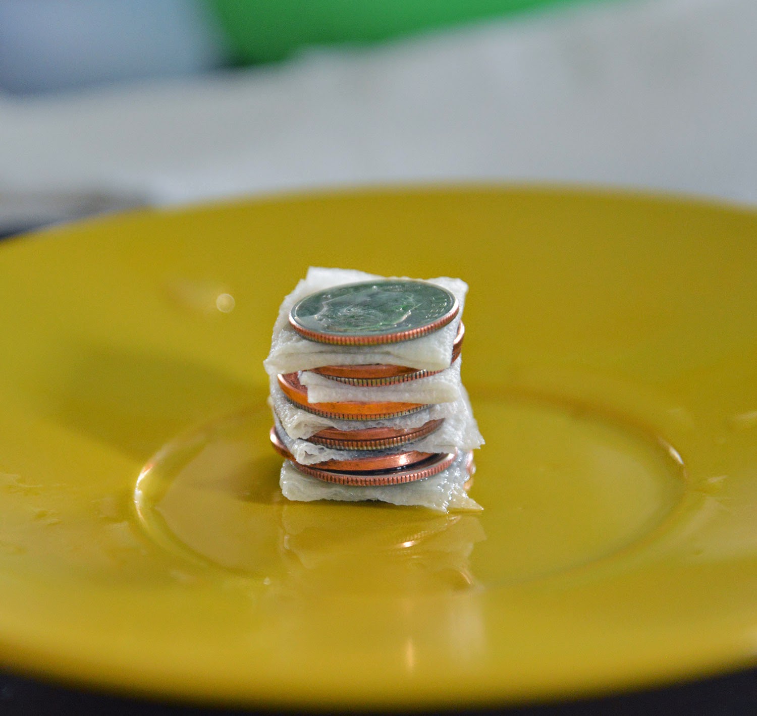
We also made a Voltaic Pile, or a homemade battery with dimes and pennies. You sandwich them with paper towel pieces soaked in lemon juice and salt, and that's enough to generate a small current. We got our instructions from a book, but here are some similar instructions online. It's a pretty simple activity.
Here you see that no current is going through (our circuit isn't complete)
Here is the current generated by our tiny battery 
And here is the measurement when the current is going through Sebby's body instead of the wire---the resistance has increased (Sebby isn't as good of a conductor as a wire is) so there is less electricity getting through.

More battery activities:

There are a million descriptions online of how to make a lemon battery; here's one.

This is a similar project to ours for a homemade battery, but it involves sanding down pennies which seemed more complicated.

This is a cool site; it has diagrams of what's inside various types of batteries (in case you are curious about the ones you can't dissect yourself!) :)

Video about how batteries work

Thursday, April 17, 2014

Homemade Light Bulb

This activity was really, really fun, and quite spectacular to watch. On the day we learned about Thomas Edison, we made our own light bulb! I didn't even know you could do that. But all you need is some electricity (8 D batteries), a holding apparatus of some sort, and a resistant material (mechanical pencil leads work perfectly). Thomas Edison, we read, tried something like 1000 different materials before coming up with a practical light bulb, so don't give up if this doesn't work the first time. :)
First, rig up your apparatus. You are just making a circuit with the pencil lead in the middle of it. So tape an alligator clip to one end of your line of batteries (which should be taped end to end), and run the other end of the wire up one side of a toilet paper tube or something similar. Clip one end of the pencil lead carefully into the "jaws" of the clip. Attach another alligator clips's jaws to the other end of the pencil lead, run the wire down the other side of the toilet paper tube, and tape the other end of the second alligator wire to the other side of the batteries, forming a complete circuit. Now your pencil lead should be suspended like a filament over the top end of the toilet paper tube. Put a glass jar upside down over the top of the whole thing.
As electricity runs through the circuit, the pencil lead will resist the current and begin to heat up and glow. This doesn't take very long (a minute, maybe?) so if doesn't start happening soon, check your circuit with a tiny light bulb or something, to make sure all the batteries are touching each other and none of the wires are faulty. It should start to smoke a bit and then glow quite beautifully.
After a short time, the pencil lead will glow very brightly and then get too hot and melt. It will break apart, opening the circuit, and that's the end of your light bulb. But you can always put in a new pencil lead and try it again and again! :)
The children were just mesmerized by their glowing homemade bulbs (and they liked the smoke and the flash as they burned out, too). This was definitely a favorite activity!

When we went to the science museum in Portland, Oregon recently, we got to see one of Edison's original bulbs (one of the ones that didn't work very well). We also saw a model of the successful bulb he made later. It was really cool to see!

Here's a video about Thomas Edison.

Speaking of Edison, here's a video that talks about the differences between AC and DC, and the contributions of Edison and Tesla to each.

Friday, April 11, 2014

Resistors and Switches

After making some simple circuits, we were ready to learn about resistors. First we made a simple "dimmer switch" using a wire coiled around a pencil. (See here for supply list.) As you move the connection up and down the coiled wire (allowing the current to either go through a lot of wire, or just a little wire), you adjust the resistance and the light gets brighter or dimmer accordingly.
We also made a circuit that included a large piece of paper towel. The paper towel provides enough resistance to the current that the electricity doesn't even get through, and the bulb won't light. But if you wet the paper towel, it provides less resistance (water helps the paper towel become somewhat of a conductor) and the bulb lights---dimly. If you sprinkle salt onto the wet paper towel, you decrease resistance even further and the light glows quite brightly!
Next, we experimented with switches. Here is a simple on-off switch using a paper clip.
My favorite was the three-way switch, which is a concept I have never before understood. This is like a room in your house where there are two switches (one at each end of the room) to turn on the same light. Here's how it works: there are basically two circuits, a short one and a long one, and two switches that toggle between the two circuits. If one switch is "up" and the other is "down," neither circuit is complete and the light is off.
If both switches are "up," the shorter circuit is complete and the light turns on.
If both switches are "down," the longer circuit is complete and the light turns on.
Amazing, eh? I love it.

Wednesday, April 9, 2014

Simple Foil Circuits; Series and Parallel Circuits; Schematics


There are a lot of cool electronics kits you can get, and in fact we had been given some snap circuit kits earlier in the year, which I'd been saving for this unit---so we could have just started right in on those. I read lots of reviews on the snap circuits talking about how educational they were, and they ARE wonderful and we have loved them---but---my one problem with them is that they are somewhat far-removed from the actual workings of the electricity. By that I mean, all the actual wiring is enclosed in snap-able components, and while that makes for ease of use, it also makes the workings of the electricity somewhat more opaque (at least to me). I think once you understand what is going on, snap circuits are great, but for an introduction to circuits, I think there are better illustrations.

So, we started with what seems to me the very most basic form of a circuit: foil and a battery! (Here is a how-to video about foil circuits, if you need it.)
First we felt how the foil gets warm as a current passes through it
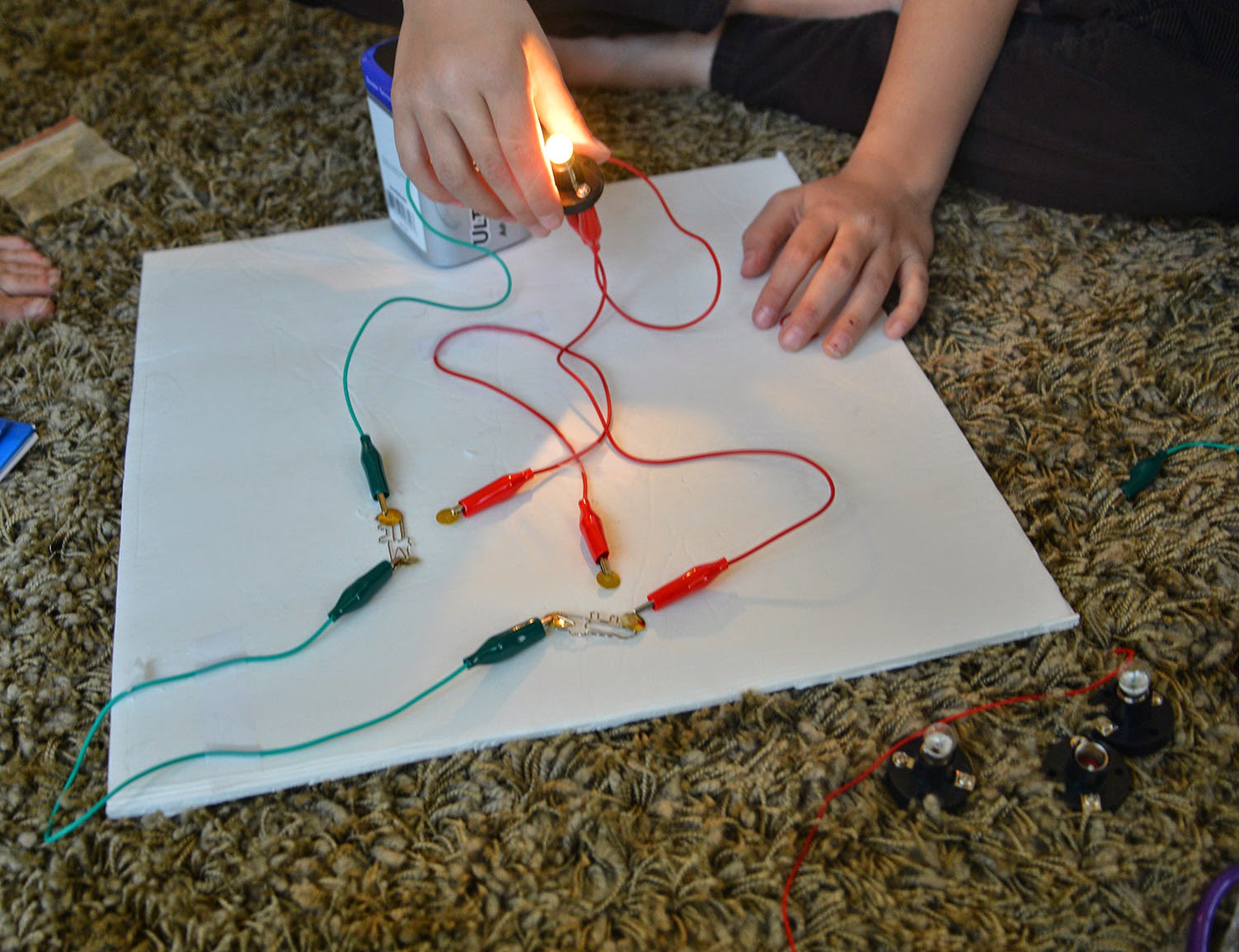
Then we added a tiny light bulb and watched it light up as electricity went through the circuit! (I will have a separate post about the materials we used for this unit.)
Next we set up circuits with batteries, bulbs, and alligator clips. We tried various configurations and learned about parallel and series circuits.
Parallel Circuit---note that the bulbs have the same brightness
Series Circuit---note the progressively dimmer bulbs as the current becomes weaker
The children also copied down a list of symbols used in wiring and circuitry schematics. They loved this---it's like a secret code!

Here are a few more resources for circuit symbols:
http://www.itclips.net/2012/04/03/going-from-schematic-to-breadboard/
http://dccircuit.wikispaces.com/01+Circuit+Symbols
http://guides.machinescience.org/mod/book/print.php?id=1312--scroll down on this page to see how a seven-segment display, like you see on digital clocks, etc, works. Very interesting.

Here's a short video about circuits

Also, these circuit worksheets from Teachers Pay Teachers are fun.

And we thought this article about circuits in your house was really interesting!

Monday, April 7, 2014

Electric current, Conductors, and Insulators

After static electricity, we went on to current electricity. First we played a game where we showed how current flows (emphasizing the point that it isn't a thing that moves along, but energy--an impulse). Everyone held a stuffed animal and we pretended the animals were electrons. You were only allowed to hold one animal at a time, so when I introduced an extra stuffed animal into the system by handing it to one of the children, they had to hand off their other animal to make sure they still only had one. We passed the "current" along the line, and then talked about how if the energy goes down a line, it has to stop when it reaches the end. But if it goes around in a circle, it can keep flowing and flowing. We also showed how an insulator works---if you insert another person into the circle, and that person CAN hold more than one electron, then when the current gets passed to him, he just holds onto it and it stops. In our game, people who easily pass electrons along are conductors, and people that hold onto electrons (or don't accept new ones) are insulators.
Then we did a lab testing different materials for their heat-conductivity. (Idea from here.) We boiled water, then poured it into identical glass jars that were wrapped with various materials, and noted the starting temperature. We then measured the temperature of the water after 20 minutes to see how much heat was kept in by the wrapping. (Our wrapping materials were foil, bubble wrap, fleece [I put felt on the lab sheet, but I couldn't find my felt so we used fleece instead], cotton cloth, paper bag, wrapping paper, and water---the jar of water was in another, bigger, jar of water.)
Here is the Lab sheet I made for us; feel free to use it.
We had a lot of fun testing these things and even some surprises (the foil was a lot better insulator than we predicted---maybe because of the air trapped in its wrinkles? or its thinness?).
Related Posts Plugin for WordPress, Blogger...